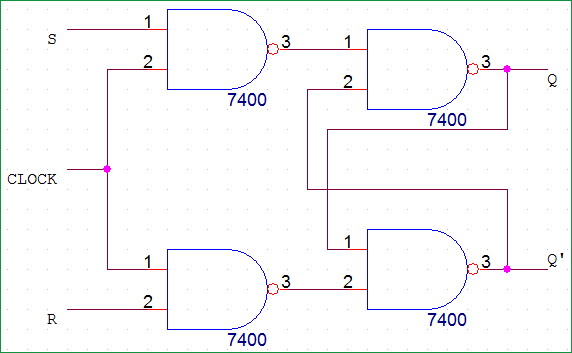
Edge Detector Circuit With Flip Flop And Or Gate : Sr latch can be built with nand gate or with nor gate.
Edge Detector Circuit With Flip Flop And Or Gate : Sr latch can be built with nand gate or with nor gate.. Shown in fig.1 consists of couple of d flip flop and an and. The circuit can be made to change state by signals applied to one or more control inputs and will have one or two outputs. Why nand and nor are called as universal gates (or) derive all other gates using only nand and difference between mealy and moore state machine. Circuit, truth table and working. A flip flop is an electronic circuit with two stable states that can be used to store binary data.
The simple rs flip flop logic circuit using two electronic logic gates is quite adequate for most purposes. And anyway there is no place for. Either of them will have the input and output complemented to each other. A characteristic equation is needed when a specific gate requires a specific output in order to satisfy the truth table. With the help of boolean logic you can create memory with them.
Chapter 10 Flipflops And Registers 1 Objectives You from slidetodoc.com The simple rs flip flop logic circuit using two electronic logic gates is quite adequate for most purposes. However, there are some generally agreed to names that cover the basic types of. Sr latch can be built with nand gate or with nor gate. Clk* must be high for ff to change states. Gate in which fvco and fref is provided as input with proposed d flip flop circuits with a 1.8v as a power supply in. Shown in fig.1 consists of couple of d flip flop and an and. The two signals will be seeking to either set or reset the circuit, and the length of time. Circuit, truth table and working.
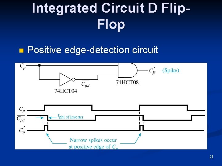
This condition only occurs at the edge of a clk transition.
This flip flop does not have a clock cycle, so it does not execute on a clock. The basic nand gate rs flip flop circuit is used to store the data and thus provides feedback from both of its outputs again back to its inputs. A conventional block diagram of phase detector circuits is. Flip flops are actually an application of logic gates. The only difference is that it has an added not gate in front of it. Sr latch can be built with nand gate or with nor gate. The result is validated in cadence. A characteristic equation is needed when a specific gate requires a specific output in order to satisfy the truth table. The two signals will be seeking to either set or reset the circuit, and the length of time. I need a edge detector circuit for clocking a 4013 flip flop. This forms a basic rising edge detector. This condition only occurs at the edge of a clk transition. The simple rs flip flop logic circuit using two electronic logic gates is quite adequate for most purposes.
It is not, however, a synchronous circuit. I need a edge detector circuit for clocking a 4013 flip flop. This forms a basic rising edge detector. The result is validated in cadence. Why nand and nor are called as universal gates (or) derive all other gates using only nand and difference between mealy and moore state machine.
Sr Flip Flop Circuit Diagram With Nand Gates Working Truth Table Explained from circuitdigest.com Sr latch can be built with nand gate or with nor gate. Circuit, truth table and working. And anyway there is no place for. A flip flop is an electronic circuit with two stable states that can be used to store binary data. This flip flop does not have a clock cycle, so it does not execute on a clock. Either of them will have the input and output complemented to each other. Check its truth table against table 1. A conventional block diagram of phase detector circuits is.
The circuit can be made to change state by signals applied to one or more control inputs and will have one or two outputs.
The circuit can be made to change state by signals applied to one or more control inputs and will have one or two outputs. A conventional block diagram of phase detector circuits is. Again, this gets divided into positive edge triggered sr flip flop and negative edge triggered sr. The result is validated in cadence. With the help of boolean logic you can create memory with them. The two signals will be seeking to either set or reset the circuit, and the length of time. You may also read more about digital logic gates. Electro tech is an online community (with over 170,000 members) who enjoy talking about and building electronic circuits. The triangle symbol next to the clock inputs tells us that these are. The only difference is that it has an added not gate in front of it. Digital design with combinatorial gates like and, or, and not gates is relatively straightforward. The circuits i describe are entirely made of 7400 series logic gates (7402, 7404 and 7408 ic). It is not, however, a synchronous circuit.
This forms a basic rising edge detector. I need a edge detector circuit for clocking a 4013 flip flop. The circuit consists of an xor2 gate, dual edge triggered flip flop and a couple of buffers. Circuit, truth table and working. Its seems that there is an error on the d flip flop drowing, eather change tha nand gates to and, or the nor to nand.
Phase Detector Wikiwand from upload.wikimedia.org The simple rs flip flop logic circuit using two electronic logic gates is quite adequate for most purposes. Googled and checked the books i have but many of the circuits shown are slightly different and. The circuit consists of an xor2 gate, dual edge triggered flip flop and a couple of buffers. The triangle symbol next to the clock inputs tells us that these are. Check its truth table against table 1. The only difference is that it has an added not gate in front of it. Digital design with combinatorial gates like and, or, and not gates is relatively straightforward. However, there are some generally agreed to names that cover the basic types of.
This forms a basic rising edge detector.
The result is validated in cadence. Electronics tutorial about sequential logic circuits and the sr flip flop including the nand gate sr flip flop which is used as a switch in other words, the output state of a sequential logic circuit is a function of the following three states, the present input, the past input and/or the past output. A flip flop relay circuit works on a bistable circuit concept in which it has two stable stages either on or off. Now that we know how a. The triangle symbol next to the clock inputs tells us that these are. Sequence detector problems like design a. And prevent timing problems caused by the asynchronous feedback from q to clk. The basic nand gate rs flip flop circuit is used to store the data and thus provides feedback from both of its outputs again back to its inputs. Shown in fig.1 consists of couple of d flip flop and an and. Either of them will have the input and output complemented to each other. A flip flop is an electronic circuit with two stable states that can be used to store binary data. The two signals will be seeking to either set or reset the circuit, and the length of time. There are lots of variations on flip flops and other sequential circuits.
Related : Edge Detector Circuit With Flip Flop And Or Gate : Sr latch can be built with nand gate or with nor gate..